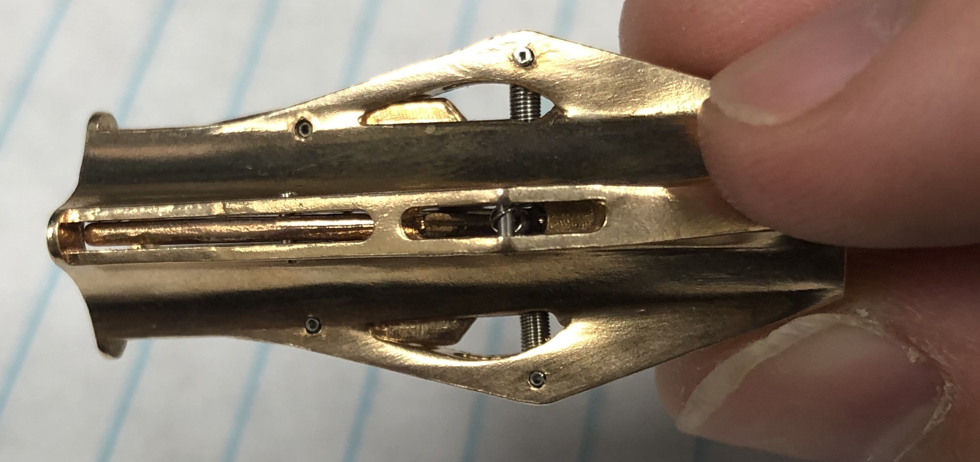
Sample Grabber Assembly
15/Sep 2020
The manipulator is used to pick up and drop off samples and tips between the shuttle in the load lock, the sample tree that is kept under vacuum, and the STM housing. Here we will go over how to build it.
Required materials:
- 3D-printed body (Autodesk Inventor and STL)
- 3D-printed pincers (Autodesk Inventor and STL)
- 1/32” x 1/8” coiled stainless steel spring pin (McMaster-Carr part #93740A005)
- 4 Extension springs, 302 stainless steel (McMaster-Carr part #1942N1)
- Wire cutters
- File
- Tweezers
These are the two 3D-printed parts:
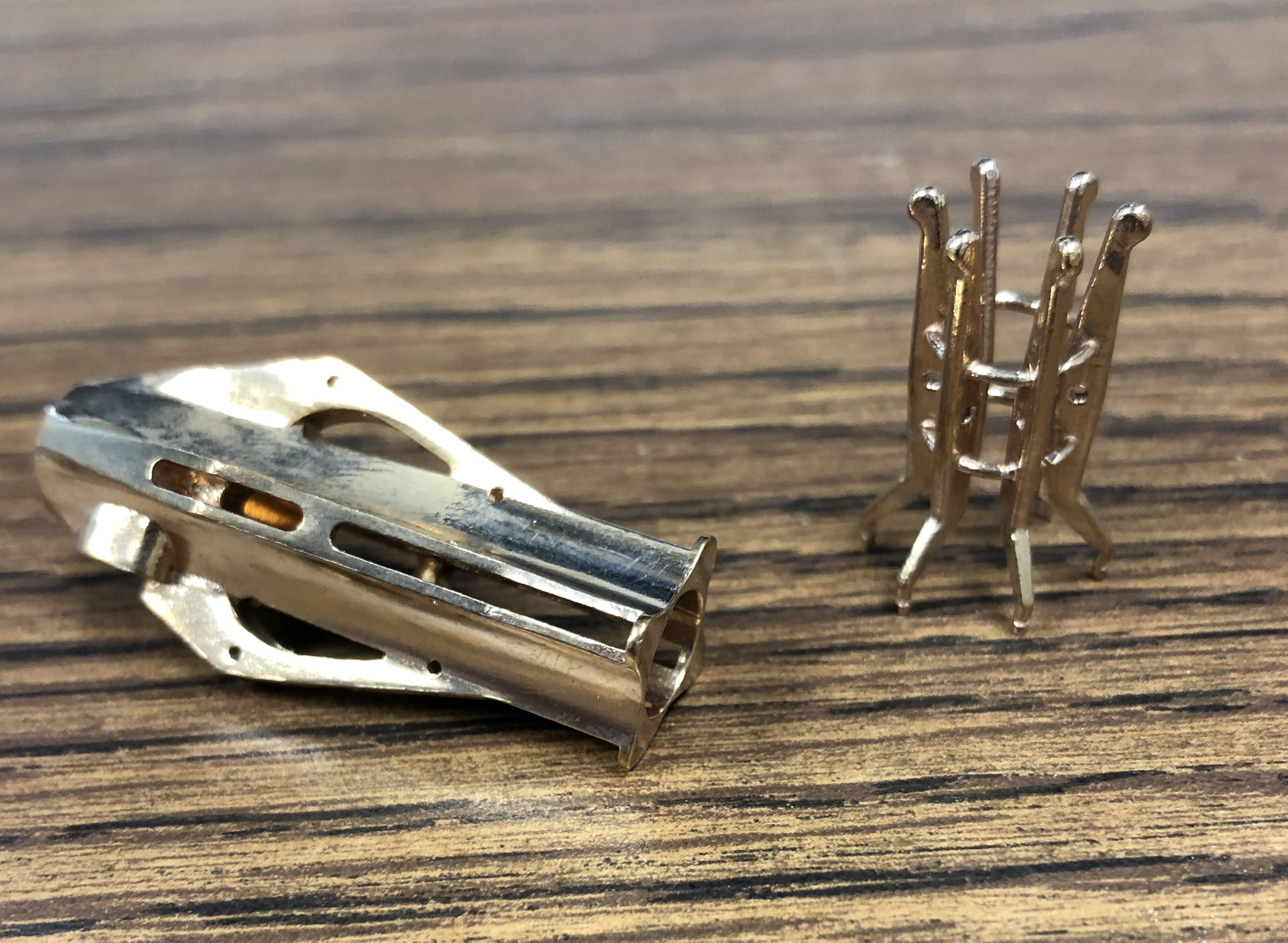
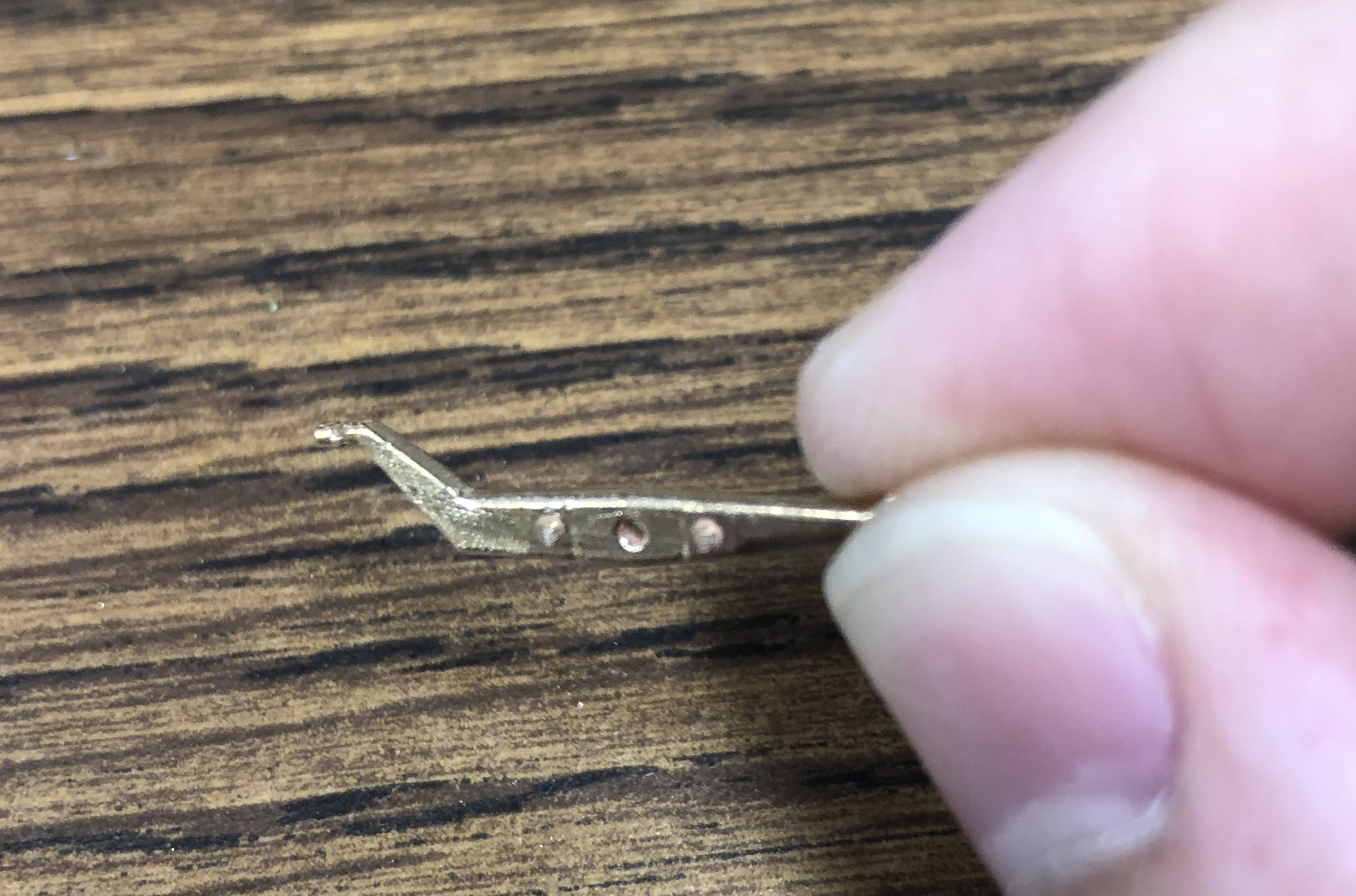
The body of the manipulator is one large piece that can be seen above. It has 4 grabbing pincers. Multiple pincers are printed as a single part, connected by sprues. The pincers must be cut out and any remaining material on the pincers has to be sanded down with a file until smooth. This allows the arms to fit into the body.
| 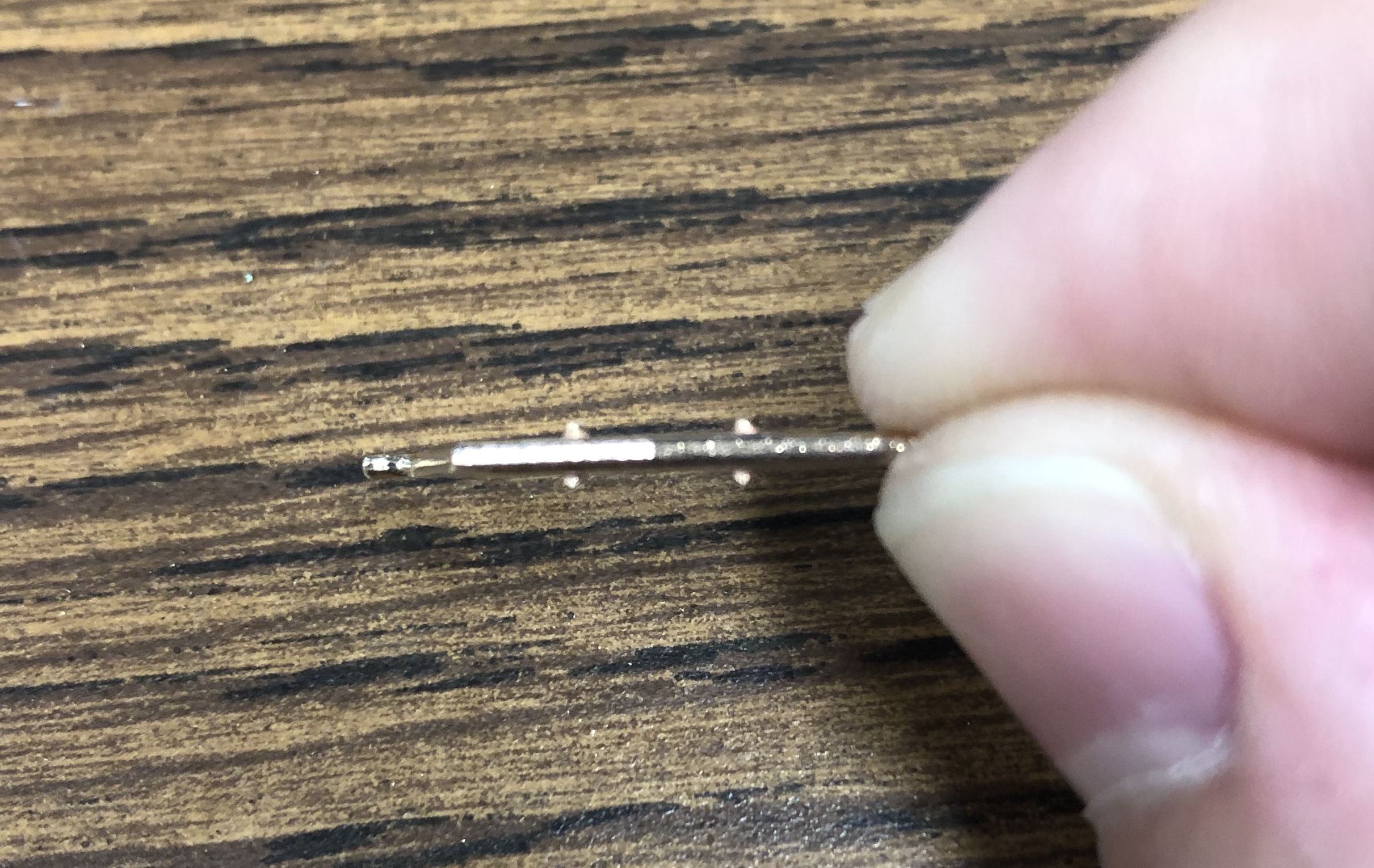 |
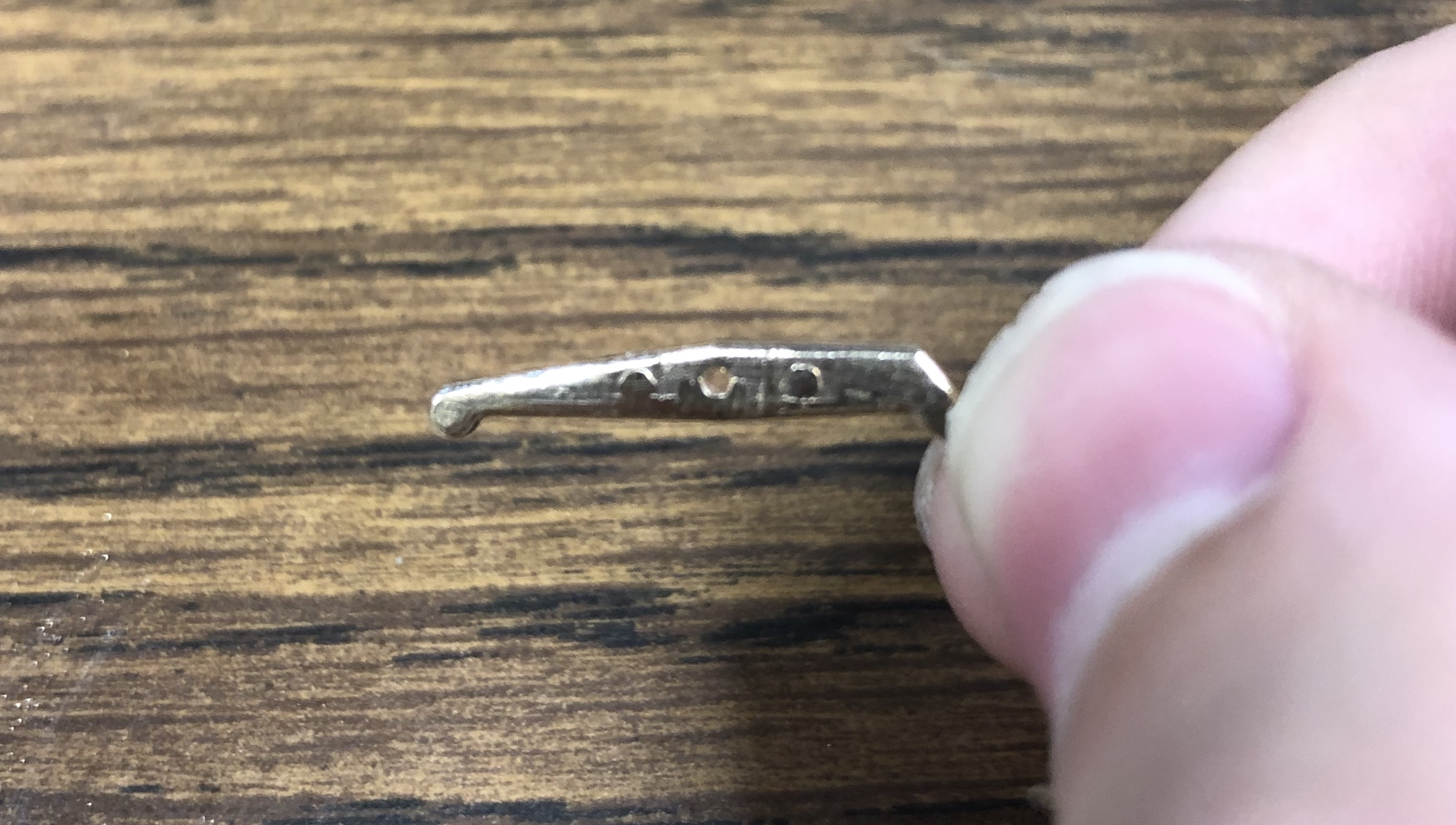
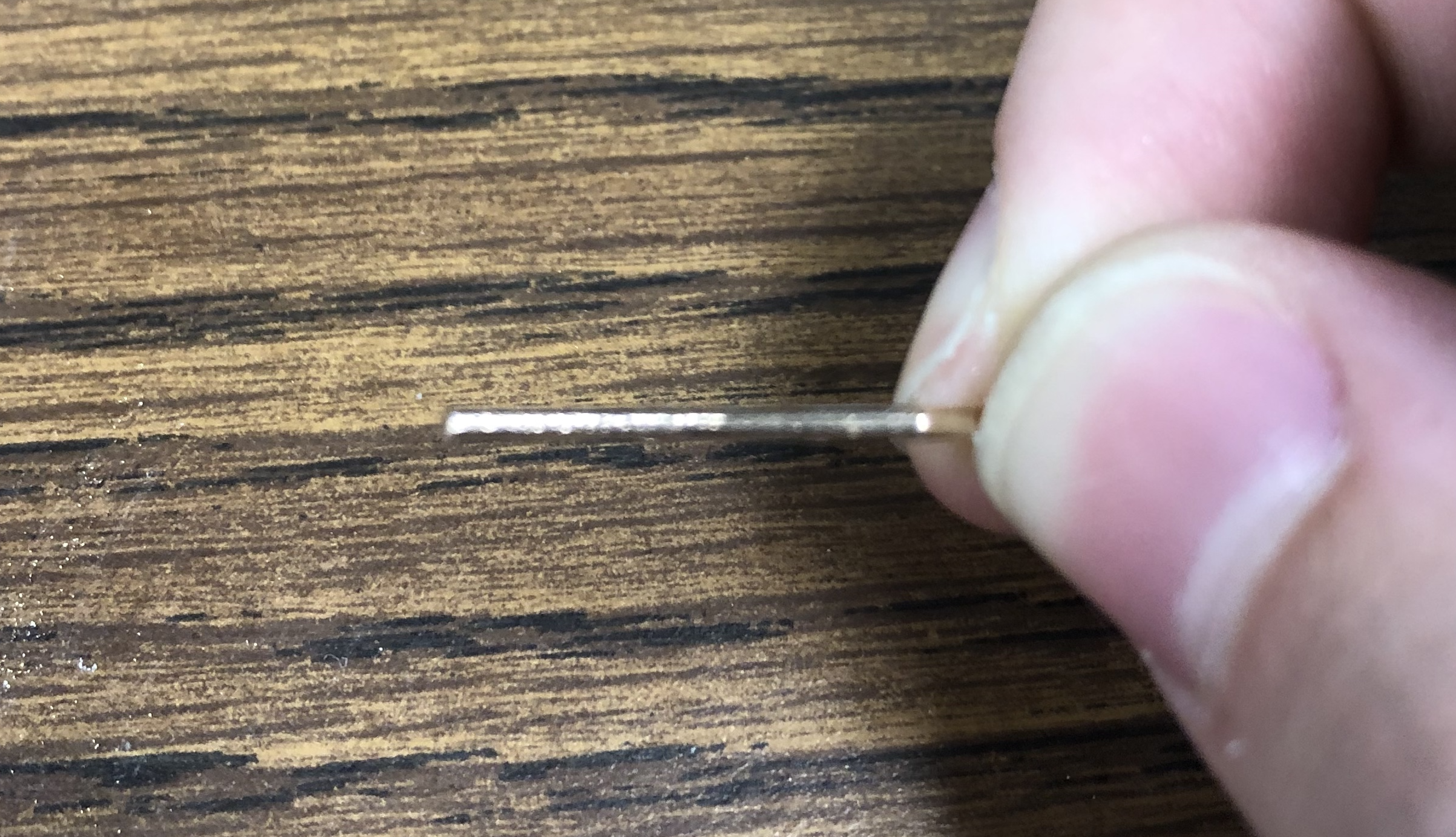
Above shows a pincer right after being cut away from the larger part with wire cutters. Below shows the pincer after filing, when it is ready to be placed in the body.
|  |
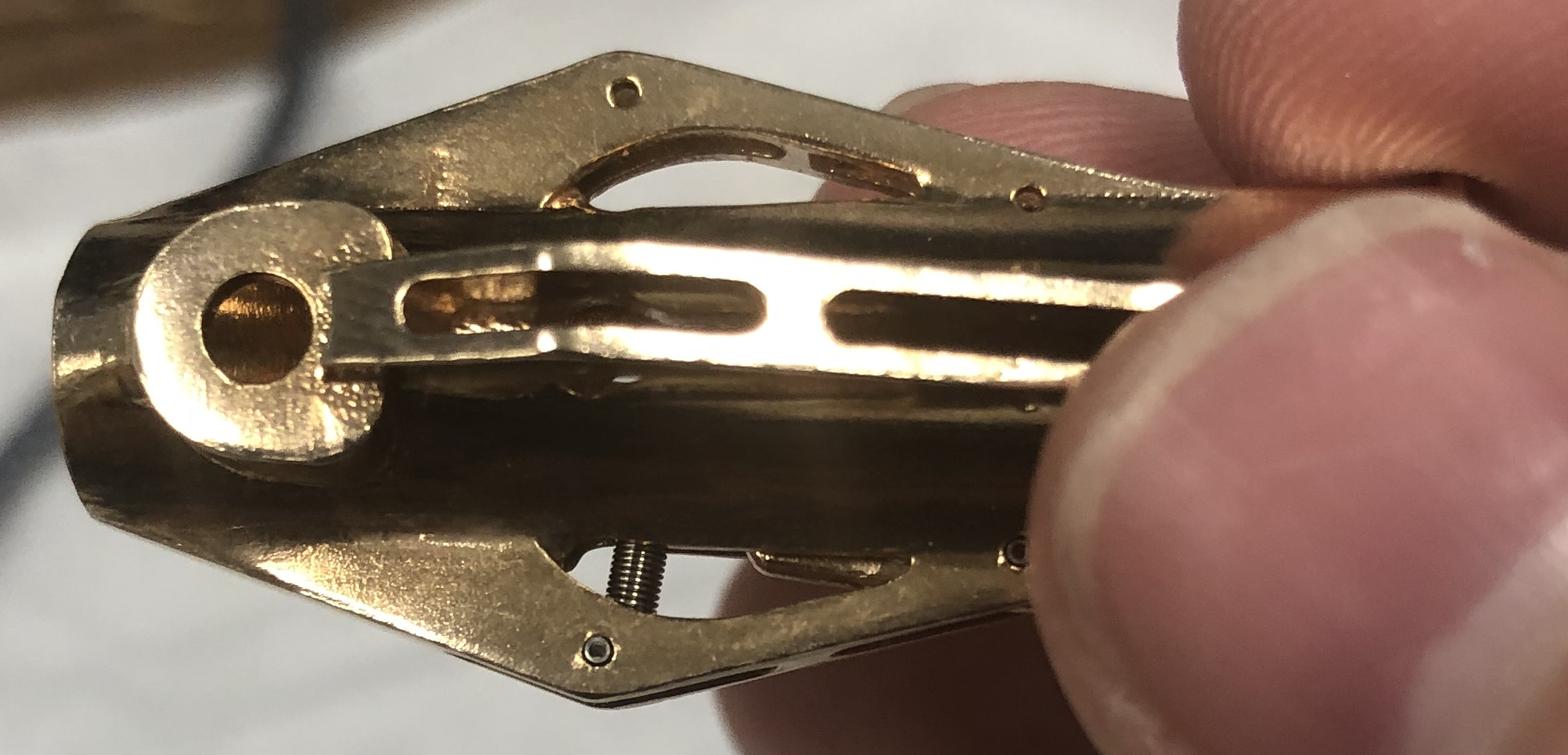
Push a coiled spring pin through one of the front holes of the grabber body. It’s good to get this one loaded before aligning the pincer as it makes it easier to get the pincer attached to the body. Slide the arm though the body through the grabber side (on the right in the image below) and align the hole of the pincer with the hole of the body. Push the coiled spring through. This will secure the pincer in the body.
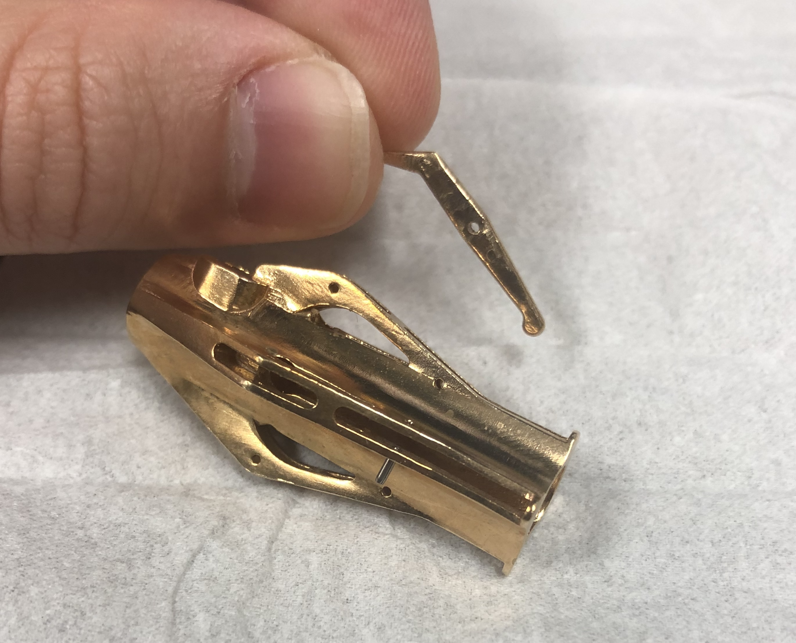
Next, feed an extension spring through the back end of the holder (the side on the left in the image below). Secure one side of the extension spring to the body using a coiled spring pin. Then loop the other end of the spring over the back of the pincer.
Repeat these steps for the other arms and then the sample manipulator will be complete.
