15/Sep 2020
2 min. read
The manipulator is used to pick up and drop off samples and tips between the shuttle in the load lock, the sample tree that is kept under vacuum, and the STM housing. Here we will go over how to build it.
Required materials: 3D-printed body (Autodesk Inventor and STL) 3D-printed pincers (Autodesk Inventor and STL) 1/32” x 1/8” coiled stainless steel spring pin (McMaster-Carr part #93740A005) 4 Extension springs, 302 stainless steel (McMaster-Carr part #1942N1) Wire cutters File Tweezers These are the two 3D-printed parts:
6/Aug 2020
3 min. read
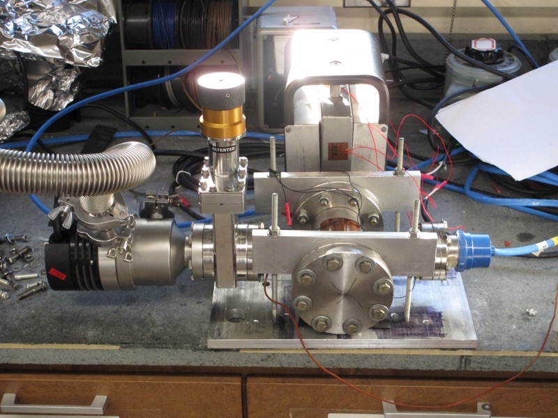
Here is the mechanism we use to load samples from our load-lock chamber to the UHV chamber. It is push-to-connect, push-to-release, which means only a single degree of freedom is needed to transfer a sample: compressing the mechanism releases a shuttle from a flange in the load-lock chamber while simultaneously attaching it to our magnetically coupled transfer arm. A second compression reverses the process, moving the shuttle off of the transfer arm and back onto the load-lock flange.
8/Dec 2017
2 min. read
Required materials: 3D printed base, legs, and plate (see this post.) 1/32” x 3/16” coiled stainless steel spring pin (McMaster-Carr part #93740A010) Ultra precision compression spring, 0.5” overall length 0.3” OD 0.256” ID 2-56 threaded 1/8” stainless steel female threaded hex standoff (McMaster-Carr part #91115A802) 2-56 socket head screw 1/4” OD stainless steel retaining ring (McMaster-Carr part #93576A100) Wire cutters File Tweezers The tip grabber discussed here was made with the intent of picking up and delivering tips from a stainless steel tip carrier (McMaster-Carr part #51755K19).
29/Jun 2017
2 min. read
Required materials: 1/32” spring pins (McMaster-Carr part #93740A005) .057” OD stainless steel compression springs (Lee Spring part #CI 006A 01 S) 3D printed base and clamps (see this post.) Wire cutters File Tweezers The sample base should be free standing while multiple clamps can be printed onto one piece. The clamps are cut out with wire cutters. There may be residual material sticking out after cutting out the piece, but the material can be filed down
26/Jun 2017
1 min. read
This is a hinged plastic clamp that attaches to the outside of a 2.75” Conflat flange, serving as a mount for a small digital camera for in-chamber inspection. We used a $15 camera (from China via Amazon) intended to be used as an after-market vehicle backup camera. It comes with built-in LED lighting and works beautifully (when it works – we bought two and one had its LEDs die after a month or so of intermittent use – but at the price we won’t complain.
12/Jun 2017
8 min. read
Preface to the tutorial: This tutorial is written in such a way that beginners to DIY electronics can follow along; more experienced builders may not need many of the steps. We’d be happy to discuss rationale for component selection and other design choices over e-mail. Also e-mail if you’d like us to send you printed circuit boards, as we have a few extras we can give away.
What you will need: Box enclosure (Hammond 1590A) Box enclosure (Hammond 1590Q) 3 printed circuit boards (see this post) Reasonably thin wire Soldering iron Solder Shunt Jumpers 3/8” 6⁄32 threaded (both sides) standoffs (x4) 1/4” 6⁄32 threaded socket head screws (x12) 1/2” 4⁄40 threaded (both sides) standoffs (x2) 1/2” 4⁄40 threaded hex screws (x4) 1/8” 2⁄56 threaded hex screws (x12) Small-pattern 2⁄56 hex nuts (x12) Electrometer Circuit: BNC Connector BNC 2-Hole standoff (3D-printed) JP2 - JP8 - M jumper pins JP1 - F jumper pins Integrated Circuits IC1 - INA116 IC2 - AMP02 IC3 - OP07D IC4 - MAX6225 Resistors R1, R2, R11 - 10 KΩ R3 - 505 Ω R4 - 20 KΩ (Trim) R5 - 5.
24/Apr 2017
1 min. read
Of all the parts of the STM, the tip grabber was probably the most difficult to design and went through the most iterations. The idea is that the grabber will be loaded into the microscope like a sample holder, at which point its pincers will open to release a tip into the microscope, or close to remove one. The pincers need to open as wide as possible, but there’s very little space for the mechanism … this is our best solution so far.
24/Apr 2017
2 min. read
This is our 3D-printed sample holder, printed in metal as a base piece and two clamping pieces. The clamps pivot on 1⁄32” spring pins (from McMaster-Carr) and derive clamping force from extremely small 0.057” OD stainless steel compression springs (from, of all places, Amazon.com).
We use a magnetically coupled linear-rotary motion feedthrough to move samples in and out of the microscope. The sample grabber here has pincers that hold onto the back knob of the sample holder.
19/Apr 2017
1 min. read
(Note, 8/6/2020: We’ve moved away from this design, because the epoxy connection between the bottom piezo cap and the silver base invariably broke when cooling the microscope down to 77 K.)
This is the single-tube STM scanner design currently in use in the Kandel lab. The tip sits in a carrier made from 1/16” OD capillary tube, and the tube rests on four ball bearings that are press fit into a metal frame.
19/Apr 2017
2 min. read
We recently published “Circuit design considerations for current preamplifiers for scanning tunneling microscopy” (link). We consider the standard feedback transimpedance design:
We considered the IC used for the operational amplifier, the composition of resistor R1, and the value of capacitor C1.
The capacitor C1 is required to prevent the circuit from going into unstable oscillations, at the cost of limiting the bandwidth of the amplifier. We found a value of 5 pF was sufficient for all of the op amps we tested, but a value of 1-2 pF could be used for the LT1169, which was also one of the lowest-noise ICs.