In-vacuum sample transfer
6/Aug 2020

Here is the mechanism we use to load samples from our load-lock chamber to the UHV chamber. It is push-to-connect, push-to-release, which means only a single degree of freedom is needed to transfer a sample: compressing the mechanism releases a shuttle from a flange in the load-lock chamber while simultaneously attaching it to our magnetically coupled transfer arm. A second compression reverses the process, moving the shuttle off of the transfer arm and back onto the load-lock flange.
It is a significant advantage to be able to accomplish sample transfer with a single motion feedthrough. A second advantage is that this motion feedthrough remains in the UHV portion of the chamber, with no feedthroughs necessary in the load-lock chamber itself. This reduces exposed surface area in the load-lock and thus improves pump-down time.
The push-to-connect, push-to-release action depends on rotation of a “spinner,” a long piece with threefold symmetry, with three radial pins. A 60-degree rotation moves the spinner from locked to unlocked or back again, depending on whether it aligns with gaps or divots in its mating piece:

| 
|
Immediately behind the pins on the spinner is a “push plate,” which is pushed forward by a strong compression spring; when locked, the shuttle is held securely between the spinner (with pins resting in the divots) and the push plate. A rotary ratchet makes the spinner rotate in one direction only and in 60-degree increments:

Now back to the main mechanism:
Compression of the rotary lock drives the spinner into the mating piece, where it encounters helical ramps that turn it 60 degrees. In cutaway:

The piece with the helical ramps can rotate, but end stops prevent it from doing so; instead, the spinner rotates as it enters the helices. When the spinner is retracted from the helices, its own ratchet prevents it from rotating back, while at the same time the helical piece rotates off the endstops, releasing the spinner.
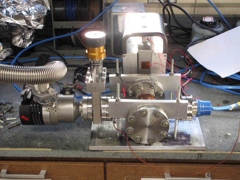
Stainless steel rods support the pieces and ensure alignment. Here is a picture of the whole thing put together:

The sample shuttle holds three samples. On each side it has a spinner and ratchet mechanism, and on each side it interfaces to a rotary lock with a helical piece. Compression of the whole thing using the magnetically coupled linear transfer arm acts to push both spinners through their respective helical ramps, rotating each spinner by 60 degrees, locking it to one side while unlocking it from the other.
On the transfer arm side, we have additional sample docks. On the load-lock side, a simple bracket bolts to the inside of a flange (use a vented screw!), holding the rods that support the rotary lock.
Here are Autodesk Inventor files for the spinner, ratchet plate, push plate, rotary housing, helical piece, shuttle, and load-lock bracket.
The STL files (for 3D printing) are spinner, ratchet plate, push plate, rotary housing, helical piece, shuttle, and load-lock bracket.