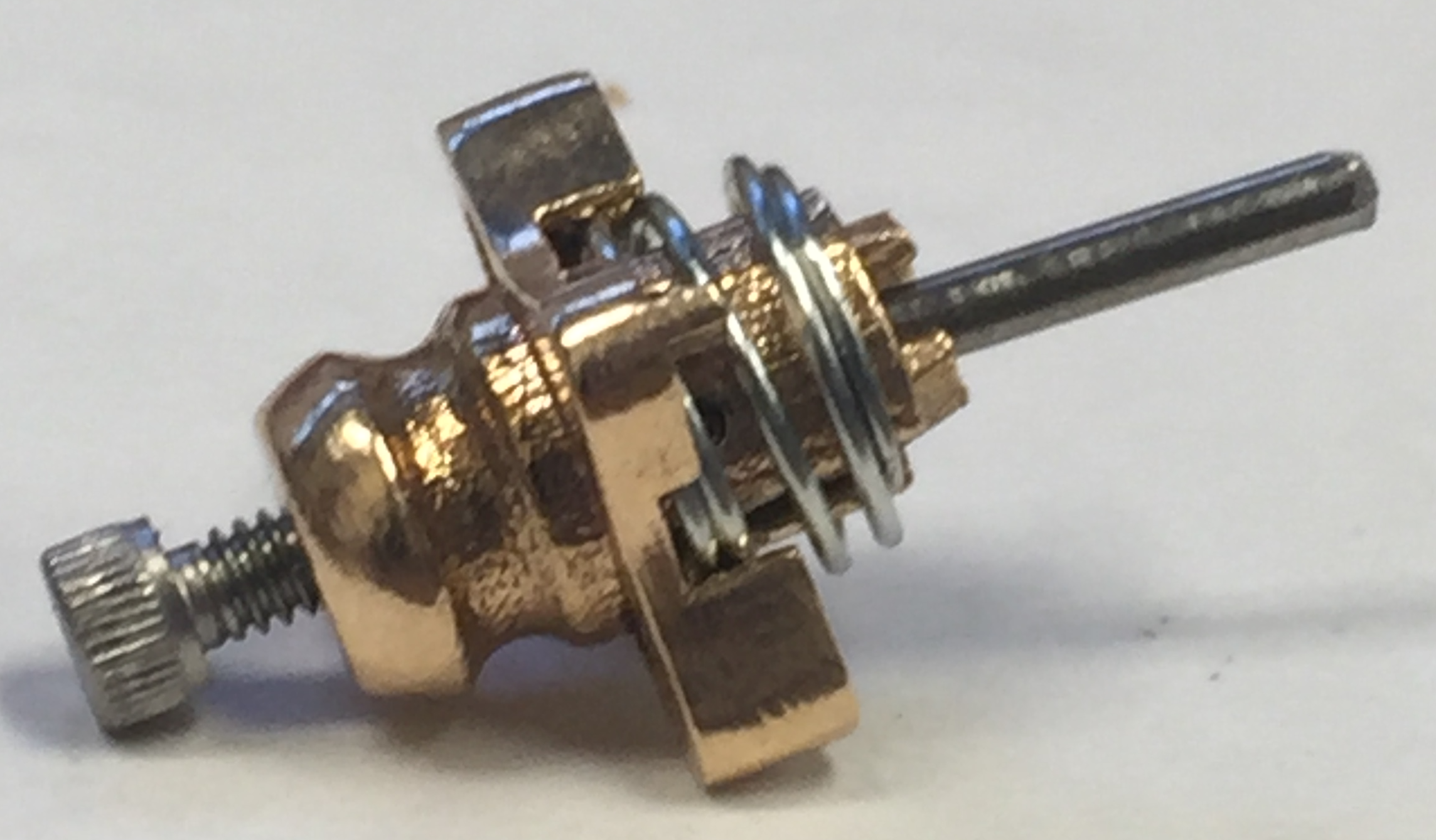
Tip grabber assembly instructions
8/Dec 2017
Required materials:
- 3D printed base, legs, and plate (see this post.)
- 1/32” x 3/16” coiled stainless steel spring pin (McMaster-Carr part #93740A010)
- Ultra precision compression spring, 0.5” overall length 0.3” OD 0.256” ID
- 2-56 threaded 1/8” stainless steel female threaded hex standoff (McMaster-Carr part #91115A802)
- 2-56 socket head screw
- 1/4” OD stainless steel retaining ring (McMaster-Carr part #93576A100)
- Wire cutters
- File
- Tweezers
The tip grabber discussed here was made with the intent of picking up and delivering tips from a stainless steel tip carrier (McMaster-Carr part #51755K19). The tip grabber base should be free standing while multiple legs and plates can be printed onto one piece.

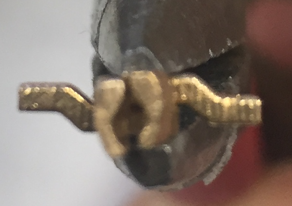
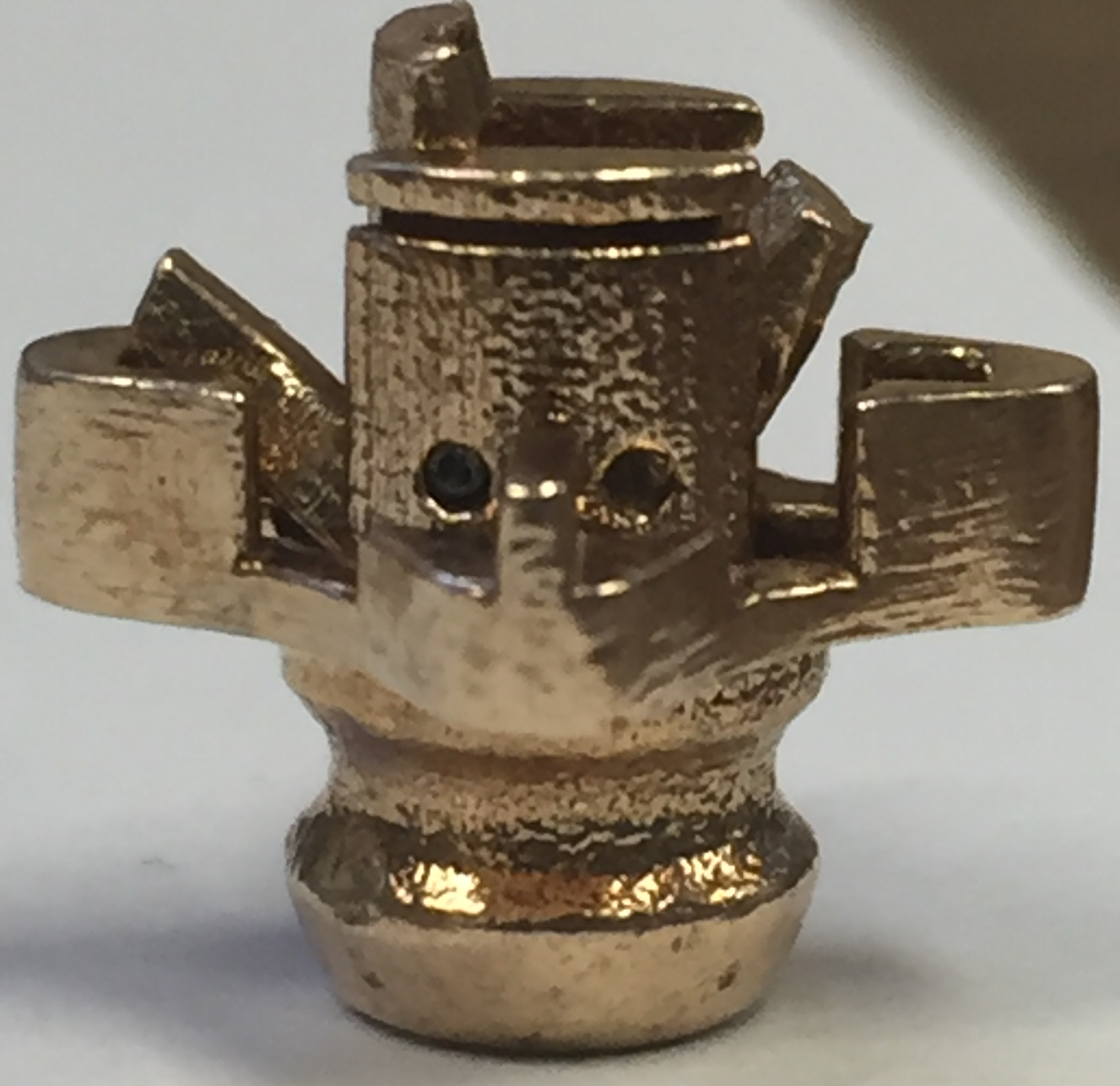
Two legs and a plate are cut out with wire cutters and any additional material is filed down. The two legs need to fit together as seen below so that they can successfully grab and drop off a tip.
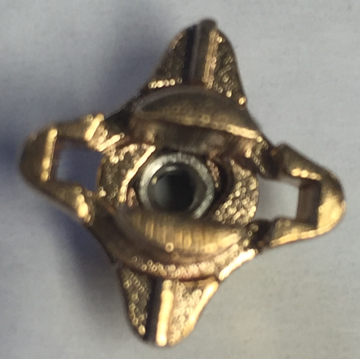
The 2-56 standoff is inserted into the tip grabber followed by the 3D printed plate as seen below.
| 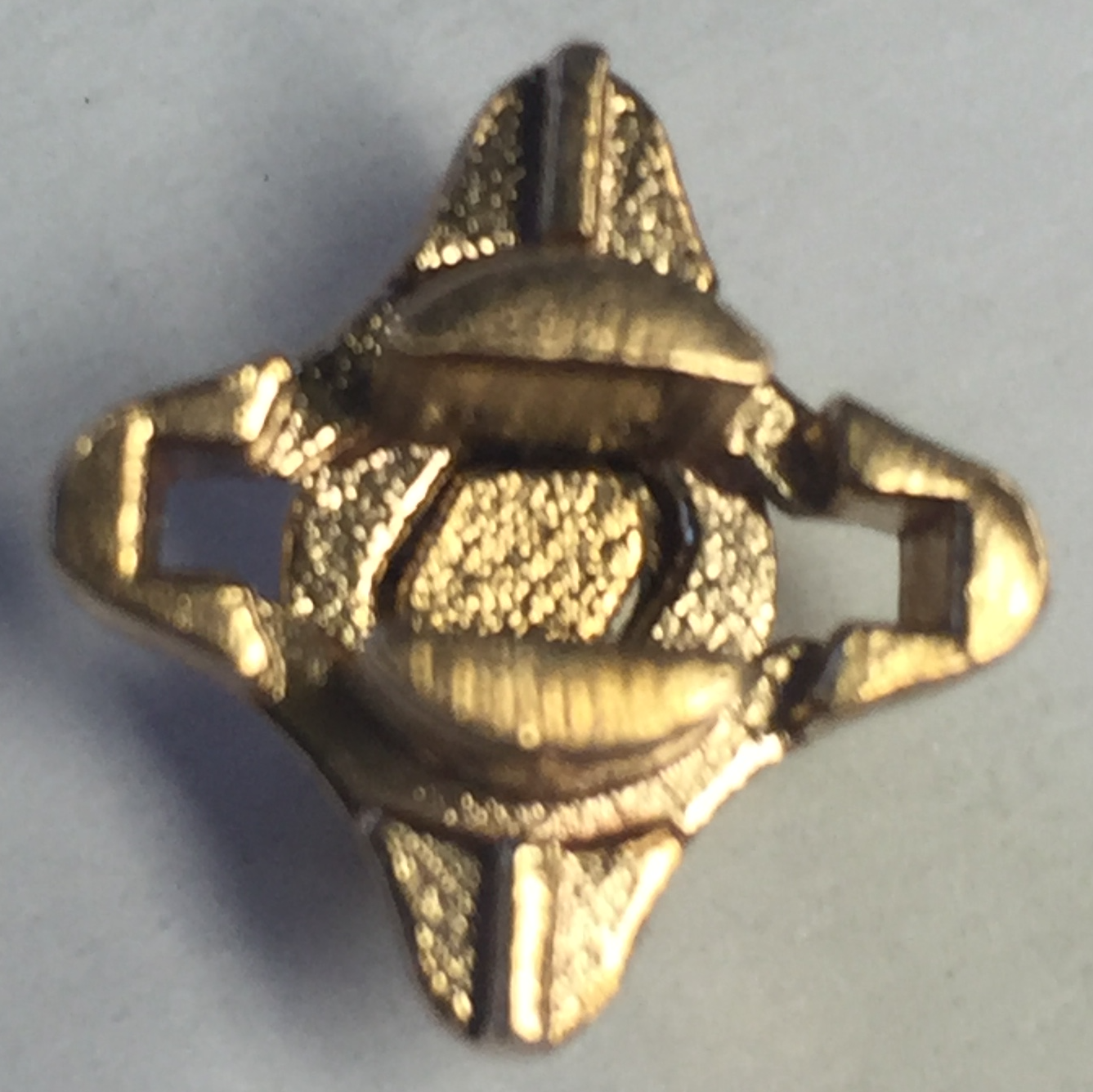 |
The legs are then inserted into the body of the tip grabber. The holes in the legs must line up with the holes in the grabber body. When those are aligned, the coiled spring pins are inserted with tweezers and pushed in.
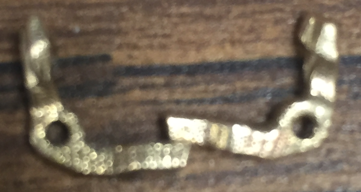
| 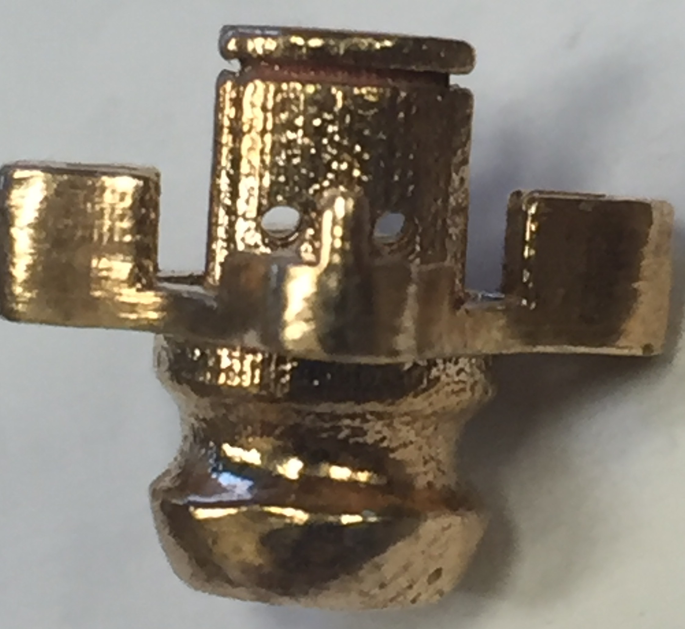 |
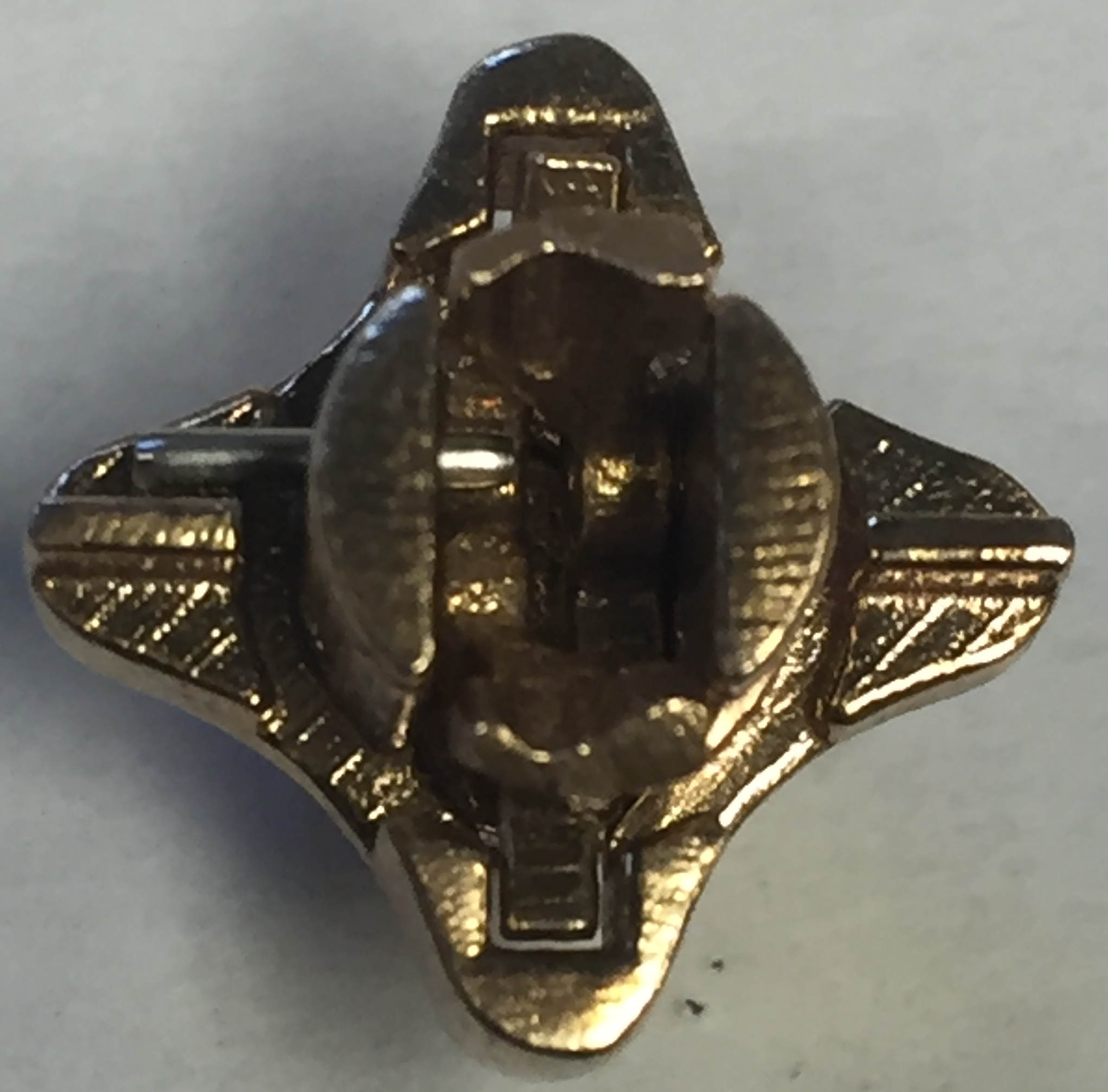
|  |
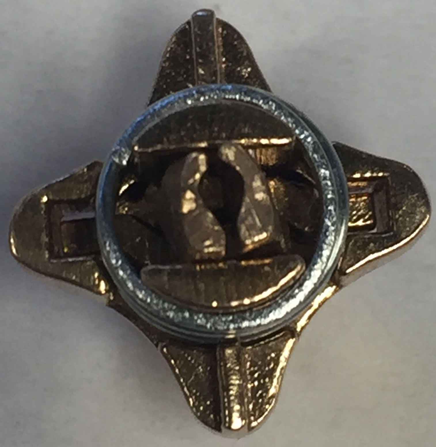
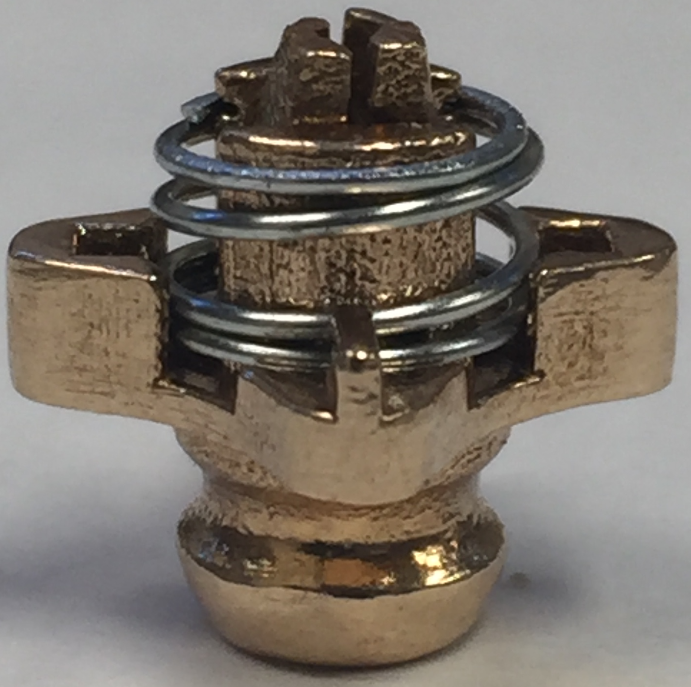
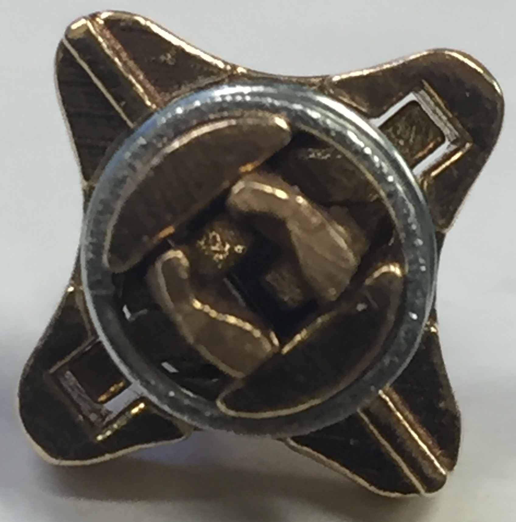
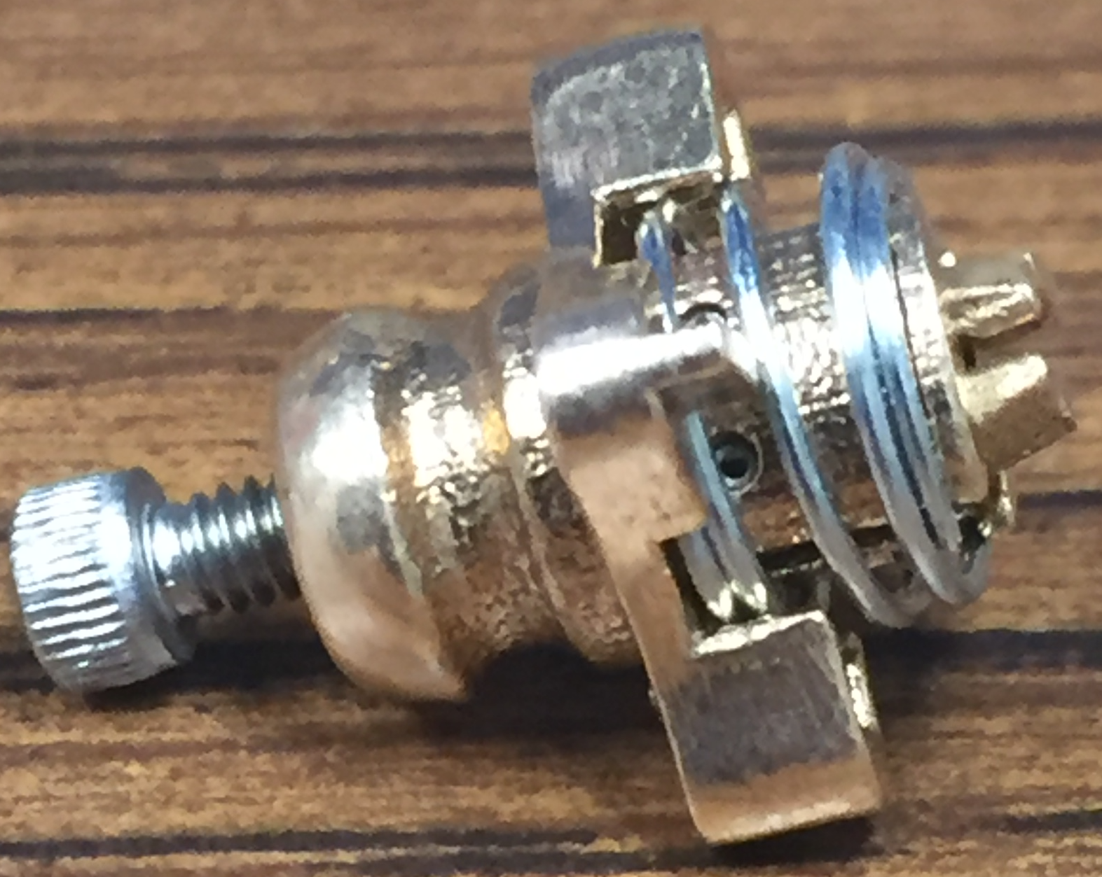
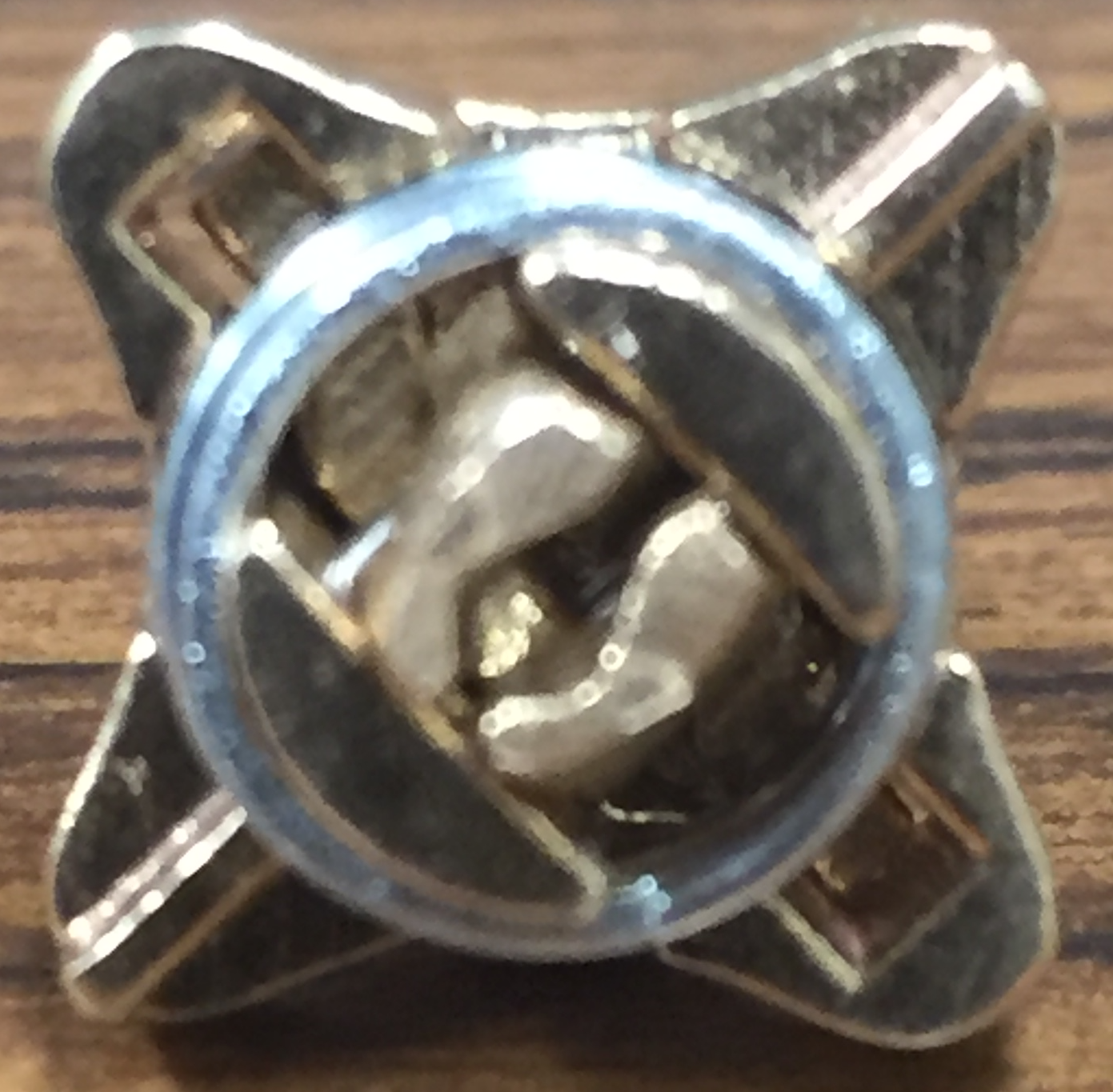
The compression spring is placed over the body. Currently, there is no great way to keep the compression spring on the body. The current solution involves crimping the end of the spring slightly so it is smaller than the end of the body it rests on. The retention ring can then be placed over the spring without being launched off the tip grabber.
|  |
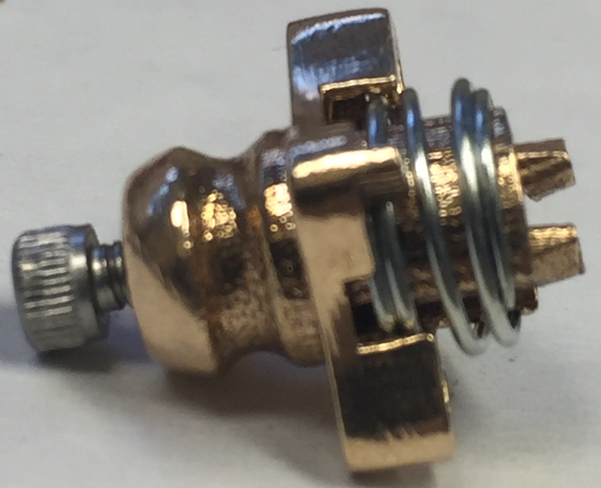
The 2-56 screw can then be screwed into the standoff from the back end of the body. Tightening the screw will cause the plate to push against the legs and cause them to open. Loosening the screw will allow the plate to be pushed back down by the compression spring, thus closing the legs.
|  | 
| 
|
Completed grabber with tip loaded:
