Transimpedance amplifiers
19/Apr 2017
We recently published “Circuit design considerations for current preamplifiers for scanning tunneling microscopy” (link). We consider the standard feedback transimpedance design:
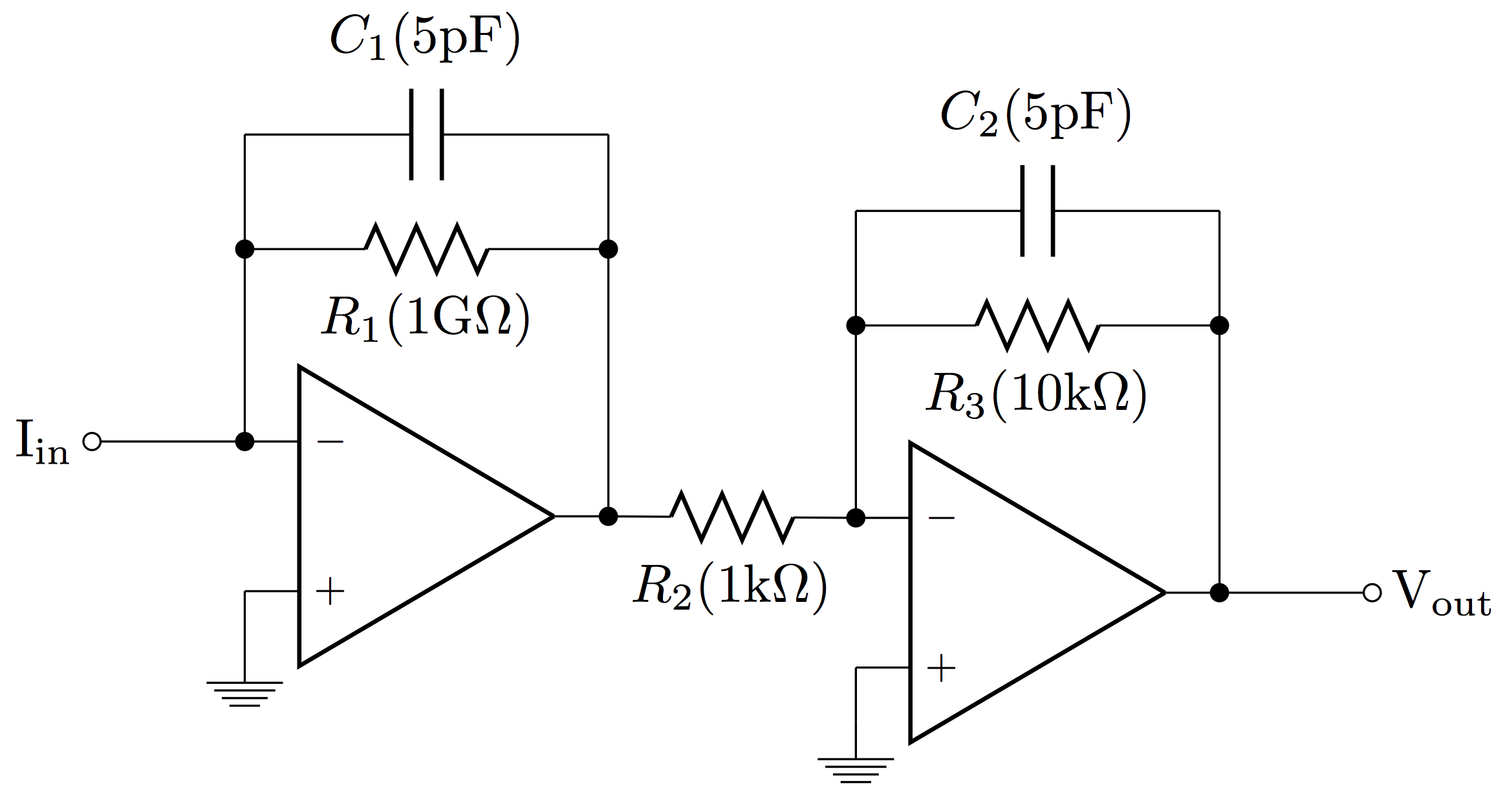
We considered the IC used for the operational amplifier, the composition of resistor R1, and the value of capacitor C1.
The capacitor C1 is required to prevent the circuit from going into unstable oscillations, at the cost of limiting the bandwidth of the amplifier. We found a value of 5 pF was sufficient for all of the op amps we tested, but a value of 1-2 pF could be used for the LT1169, which was also one of the lowest-noise ICs. The composition of the feedback resistor did not affect circuit performance.
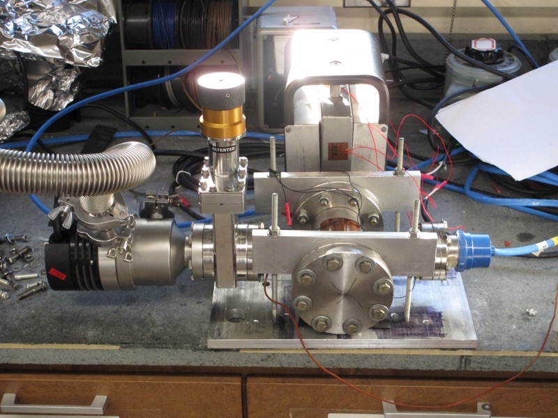
The surprise in this study is how well the electrometer design performed:
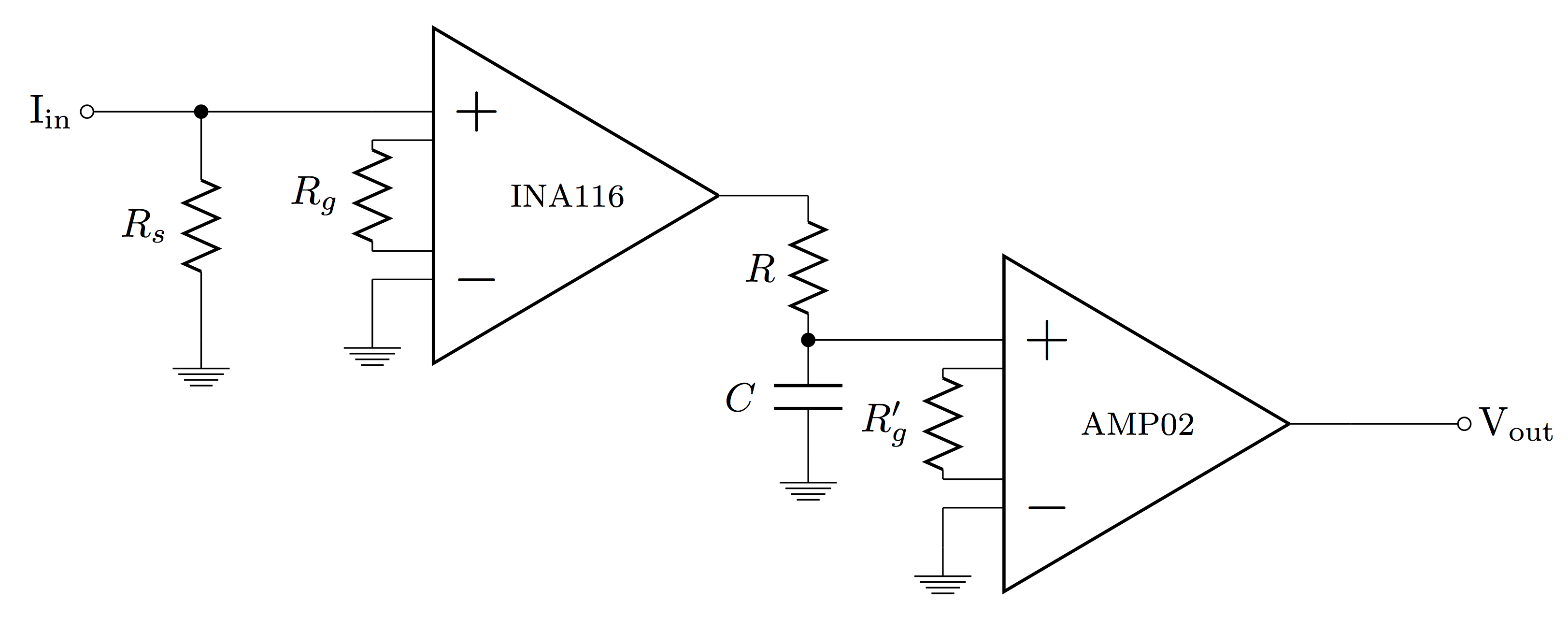
We worked from this paper, and found the circuit beat the feedback transimpedance amplifier, with lower noise at comparable bandwidths, or higher bandwidth at comparable noise. The circuit is stable without the need to fiddle with a feedback capacitor, and the INA116 instrumentation amplifier has extremely low input bias current as well as overvoltage-protected inputs.
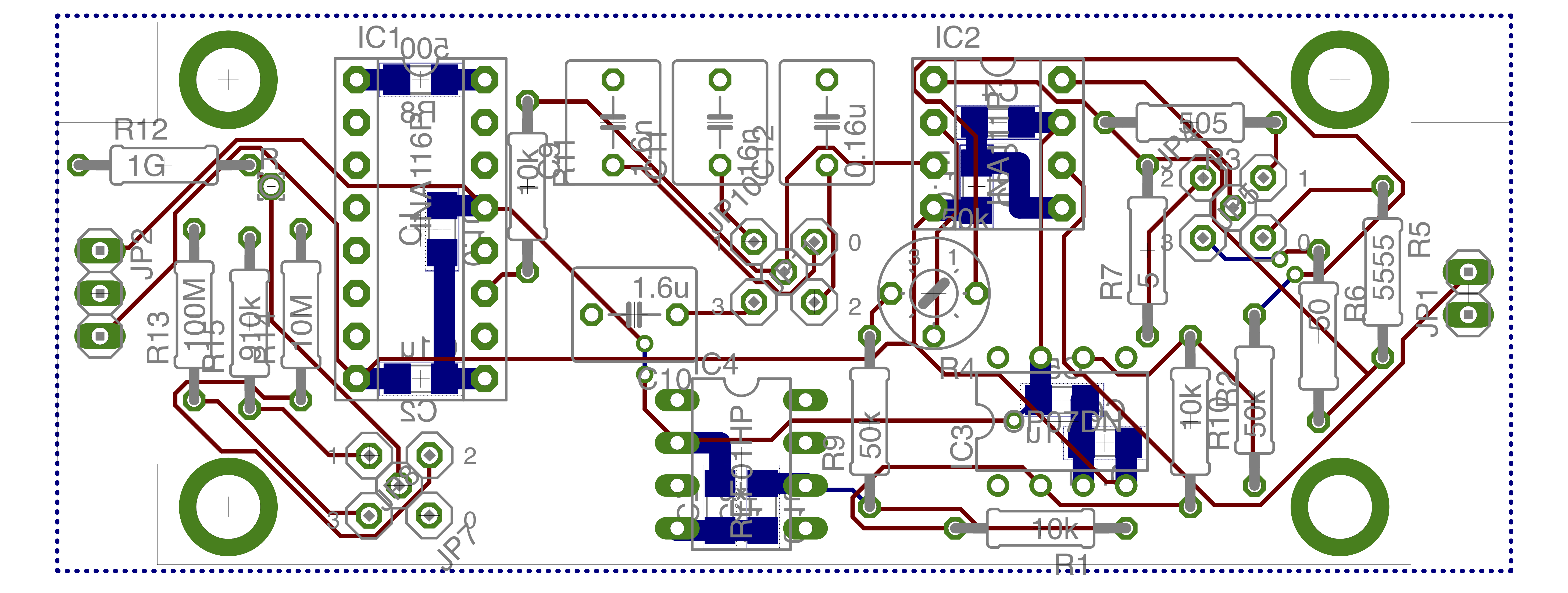
Here are the EAGLE files for putting together an electrometer:
- Electrometer schematic and board
- Voltage regulator and battery check schematic and board
- Switch and connector for batteries schematic and board
BOM and detailed assembly instructions are posted here.